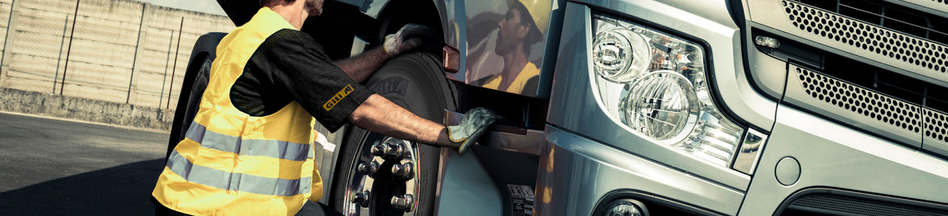
Tire Care
-
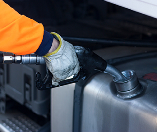
FUel Efficiency
Save amounts of fuel for your business. -
Maximizing TIre Life
Take care of your truck tire lifespan. -
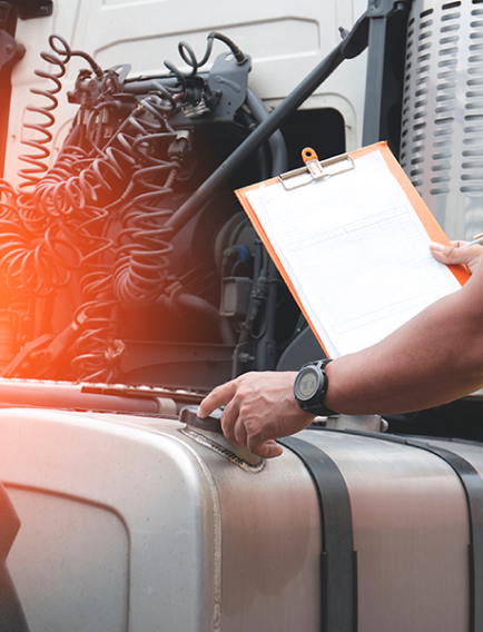
Did you know
Maximize your knowledge about tire trucks. -
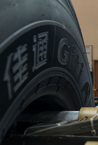
Commercial Tire Basics
Understand the Specifications.
A starting point to learn more about tires, especially relating to trucks and busses. Discover how to understand tire specifications, the difference between tube and tubeless tires, and more.
Contact Us
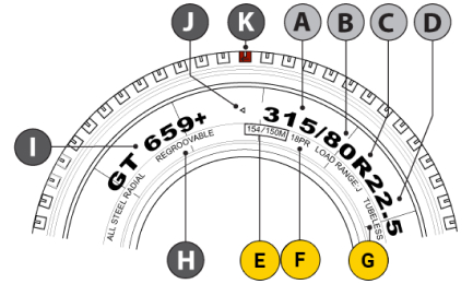
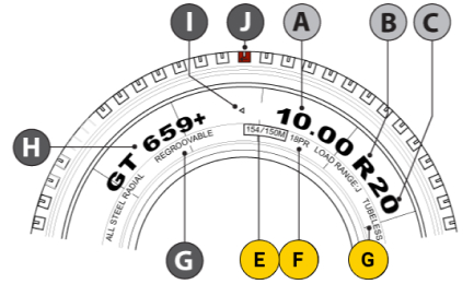
2 Common Standard Tire Sizes
-
ANominal Section Width (mm)
-
BNominal Aspect Ratio
-
CRadial Structure Code
-
DNominal Rim Diameter (in)
-
E154/150M
154 - Load Index (Single)
150 - Load Index (Dual)
M - Speed Rating -
FPly Rating
-
GTubeless Tire
-
HNominal Section Width (mm)
-
INominal Aspect Ratio
-
JRadial Structure Code
-
KNominal Rim Diameter (in)
Appropriate Speed Rating with the corresponding Load Index
-
ANominal Section Width (in)
-
BRadial Structure Code
-
CNominal Aspect Ratio
-
E154/150M
154 - Load Index (Single)
150 - Load Index (Dual)
M - Speed Rating -
FPly Rating
-
GTubeless Tire
-
GRegroovable Indicator
-
IPattern Name
-
JBelt Winding Direction
-
KTire Rolling Direction
The table below lists the appropriate speed rating with the corresponding load index
Load Index
| LI | kg |
|---|---|
| 115 | 1215 |
| 116 | 1250 |
| 117 | 1285 |
| 118 | 1320 |
| 119 | 1360 |
| 120 | 1400 |
| 121 | 1450 |
| 122 | 1500 |
| 123 | 1550 |
| 124 | 1600 |
| LI | kg |
|---|---|
| 125 | 1650 |
| 126 | 1700 |
| 127 | 1750 |
| 128 | 1800 |
| 129 | 1850 |
| 130 | 1900 |
| 131 | 1950 |
| 132 | 2000 |
| 133 | 2060 |
| 134 | 2120 |
| LI | kg |
|---|---|
| 135 | 2180 |
| 136 | 2240 |
| 137 | 2300 |
| 138 | 2360 |
| 139 | 2430 |
| 140 | 2500 |
| 141 | 2575 |
| 142 | 2650 |
| 143 | 2725 |
| 144 | 2800 |
| LI | kg |
|---|---|
| 145 | 2900 |
| 146 | 3000 |
| 147 | 3075 |
| 148 | 3150 |
| 149 | 3250 |
| 150 | 3350 |
| 151 | 3450 |
| 152 | 3550 |
| 153 | 3650 |
| 154 | 3750 |
| LI | kg |
|---|---|
| 155 | 3875 |
| 156 | 4000 |
| 157 | 4125 |
| 158 | 4250 |
| 159 | 4375 |
| 160 | 4500 |
| 161 | 4625 |
| 162 | 4750 |
| 163 | 4875 |
| 164 | 5000 |
| LI | kg |
|---|---|
| 165 | 3875 |
| 166 | 4000 |
| 167 | 4125 |
| 168 | 4250 |
| 169 | 4375 |
| 170 | 4500 |
| 171 | 4625 |
| 172 | 4750 |
| 173 | 4875 |
| 174 | 5000 |
| LI | kg |
|---|---|
| 175 | 6900 |
| 176 | 7100 |
| 177 | 7300 |
Speed Rating
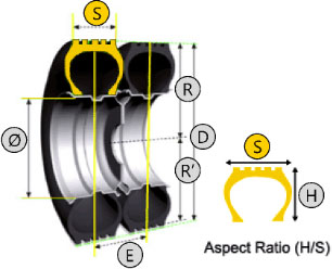
Tire Dimensions
-
SSection Width
-
HSection Height
-
RFree Radius
-
RLoaded Radius
-
EDistance Between Dual Tires
-
DFree Diameter (R x 2)
-
QRim Diameter
Load index is subject to the driving speed, tire structure, and tire mounting position (single or dual). The US TRA, Korea KS, EU ETRTO, and Japan JIS standards all follow the same load index.
The table below shows the smallest index under cold tire conditions.
Air pressure can be appropriately increased under the following conditions
-
AIncrease speed and load requirements
-
BFor better handling
However, the increased air pressure should not exceed the specified maximum load, 20 psi, nor exceed the maximum load and air pressure required by the rim.
Over inflation will lead to tire blowout which affects driving safety and increases operating costs!
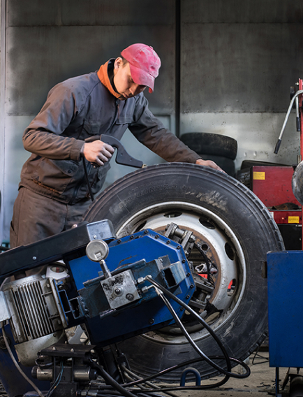
Steps by steps guide of how to properly repair your truck tire.

First, inspect the tire thoroughly to determine if it is repairable.

If any damage is found, mark the position both inside and outside with a crayon.

Remove the foreign object that caused the damage.

Check if there is any hidden damage inside or outside with a puncture probe.

Determine the damage angle from inside out with a drill bit.

If the damage is greater than 25°, use the two part separation method to repair. If the diameter of the damage is within 15 mm, use an integral radial plug.

Align the center of the repair material with the center of the damage, and draw a peripheral line 25 mm beyond the repair material as the buffing line.

Spray the area with a rubber cleaner.

When the tire is still wet, scrape off the foreign objects with a scraper.

Use a rubber buffing wheel and a low-speed pneumatic buffing machine to buff the previously marked area.

Use a carbide cutter and a low-speed pneumatic drill to cut along the damaged area from inside to outside in a clockwise direction for at least three times.

Repeat step 11 from outside to inside for three times to make sure the damaged area is properly treated.

Use a vacuum cleaner to remove the steel slag and scrap rubber on both sides of the tire.

Use the rubber cleaner and a clean cloth to remove the contaminants by wiping the tire outward from the center. Repeat this step until the buffed area is completely clean. Wait 3-4 minutes for the cleaner to completely dry.

With a brush, apply the curing agent both inside and outside the buffed hole.

Apply the curing agent on the buffed area outward from the center, and wait 3-5 minutes for it to dry.

Position the steel string puller around the middle of the exposed black rubber stem.

Remove the blue film wrapping the rubber stem.

Remove the blue film from the crown and reposition it (see picture). This is to avoid unnecessary adhesion during the pulling process and contamination of the grey cushion gum.

Position the integral radial plug horizontally, and apply the curing agent on the cone part of the rubber stem and on the edge of the gray adhesive.

Drill the steel string puller through the hole paying special attention to the alignment of the arrow with the tire toe.

Pull the steel string puller from the inside out so that the integral radial plug is secured in place.

After the rubber stem is pulled out of the hole, check if arrow 5 is aligned with the tire toe. Continue pulling until the reinforced crown is pressed against the inner tire surface.

Use your thumb to press the crown into position.

Use a compaction roller to secure the crown in place from the center out.

Remove the blue film and repeat the step above until the crown is completely compacted.

Remove the white film.

Apply safety sealant to the crown and along the polished site, when tubeless tire is repaired.

Cut the rubber stem so that it is leveled with the tread. If the rubber stem is in the groove, use a carving machine to carve it so that it matches the tread.

The repair process is completed, and the tire can now be put back into service.
Steps by steps guide of how to properly repair your truck tire.

The tire and tube should be cleared of debris before assembly. It is recommended to apply dry and finely grounded talc or graphite powder uniformly on the surface of the tire inner wall, tube, and flap.

When placing the folded tube into the tire, the valve stem must be face upwards. Unfold and flatten the inner tube when inserting it into the tire. Remove the tube valve cap.

Check if the flap is assembled in the correct position. Set the flap on the tube valve stem, between the tube and the tire. Make sure there are no wrinkles or folds on the flap edge.

Apply noncorrosive lubricants uniformly on the bead. Install the tire onto the rim, aligning the valve with the rim valve slot.

Insert the ring (compression ring) into the groove.

Make sure all the components are properly installed and match with each other. Remove the tube valve core and inflate the tire pressure to the recommended 350 kPa. Using a wooden mallet, tap along the tire circumference so that the tire fits tightly with the rim.

Check to see if the tire is installed correctly. If not, deflate the tire and readjust the position of the tire and the rim.

After the tire is assembled, check to see that each component is installed properly before inflating the tire. Then inflate the tire to the specified pressure level and measure with a pressure gauge.
Notes:
Tires must be installed on specified rims. The rims cannot be deformed, rusted, non-circular, cracked, unevenly welded, loosed, or sharp-edged.
Only tires with the same specification, structure, brand, size, ply rating, and pattern can be installed on the same axle.
Install directional tire so that the rotation direction is consistent with the vehicle’s traveling direction.
When replacing new tires, it is recommended to replace all the tires on vehicle or at least on the same axle.
Use special tools or machinery to install and remove tube tires.
During tire inflation, the operator should not stand to the side of the tire.
Steps by steps guide of how to Remove and Install your Tubeless Tire Truck.

Choose the correct rim size and model for your tire. It is recommended to replace the rim if there are damages or cracks.

Clean the rim with clean cotton towels.

Tighten the valve stem cap to prevent the valve from loosening and leaking air.

Apply noncorrosive lubricants uniformly on the bead. Install the tire onto the rim by aligning the valve with the rim valve slot.

Check if the tire is damaged or cracked. If so, replace or repair the tire immediately. Clean the tire (recommend using special tire cleaners) by wiping off the moisture or debris inside the tire with a clean cotton towel.

Use lubricants to protect the tire from damage. Lubricate the bead and rim edge uniformly.

Align the balance point (white dot) with the valve, tilt the tire to place it onto the rim, and fix the rim in place using splints.

Insert the indenter from the bottom of the rim and rotate the main axle clockwise. Never install both beads at the same time to avoid bead damage.

Inflate the tire to the recommended pressure of 350 kPa. Check to see if the tire is installed correctly (tire line matches up with rim edge). If not, deflate the tire and readjust the position of the tire and the rim.

After the tire is assembled, check to see that each component is installed properly before inflating the tire. Then inflate the tire to the specified pressure level and measure with a pressure gauge. During tire inflation, the operator should not stand to the side of the tire.
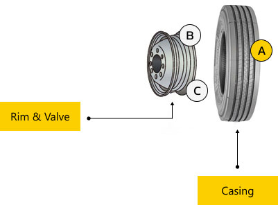
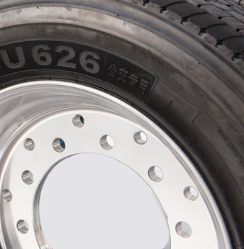
Tubeless Tire Features & Basic Components
-
AOuter diameter of a tubeless tire is the same as a tube tire, so the gear ratio will not change before or after a tire change
-
BRim diameter is 2 inches wider with better heat dissipation and lower temperatures
-
CLoad capacity remains the same with a lighter rim
Advantages of Tubeless Tires: 10% Lighter Than Tube Tires
 Lower sidewall for more accurate and safer steering and handling
 Fewer components with lower friction and rolling resistance for better fuel efficiency
 Superior heat dissipation and lower temperatures for longer tire life
 Better contact area with uniform wear for longer tire life
 Less components and lighter weight for reduced fuel consumption
Your Table Guide of Tire Specifications for your Tire Truck
| Bias Tire | Radial Tire |
|---|---|
| 7.00-16 | 7.00R16 |
| 7.50-16 | 7.50R16 |
| 8.25-16 | 8.25R16 |
| 7.50-20 | 7.50R20 |
| 8.25-20 | 8.25R20 |
| 9.00-20 | 9.00R20 |
| 10.00-20 | 10.00R20 |
| 11.00-20 | 11.00R20 |
| 12.00-20 | 12.00R20 |
| 90 Series | 80 Series | 75 Series | 70 Series | 65 Series |
|---|---|---|---|---|
| 8R17.5 | / | 205/75R17.5 | / | / |
| 8.5R17.5 | / | 215/75R17.5 | / | / |
| 9.5R17.5 | / | 235/75R17.5 | 245/70R19.5 | / |
| 8R22.5 | / | / | / | / |
| 9R22.5 | / | / | / | / |
| 10R22.5 | / | / | 255/70R22.5 | / |
| 11R22.5 | 275/80R22.5 | 295/75R22.5 | 275/70R22.5 | / |
| 12R22.5 | 295/80R22.5 | / | / | 385/65R22.5 |
| 13R22.5 | 315/80R22.5 | / | 315/70R22.5 | 425/65R22.5 |
Disclaimer
This Specification Guidance Table for Replacement is only for reference. Giti does not assume any responsibility for it. When replacing tires, please consult with your local distributor and take into consideration the rim, tire specification, load, handling, and other factors.
Giti Tires are built to last for long distances. Here you can find more ways to care for your truck tire lifespan, with an emphasis on tire pressure, tire rotation, retreading, and other factors that affect wear.
Contact Us
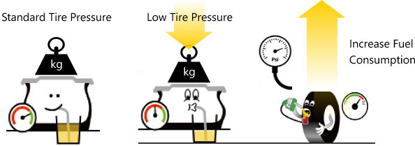
Why Should We Perform Regular Tire Pressure Checks?
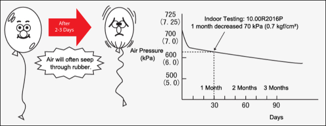
Importance of Regular Tire Pressure Inspection
- Tire Pressure will naturally decrease over time.
- New tire will decrease 70 kPa (0.7 kgf/cm2) within a month.
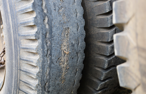
Dangers of Low Tire Pressure
 Abnormal Shoulder Wear On Both Sides
 Deformed Sidewalls (Steel Wire Detaches From Rubber)
 Sidewalls Easily Broken
 Increased Fuel Consumption
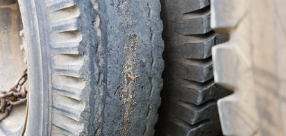
Tire Damage
- Decreased buffering capacity and shock resistance leads to more broken steel wires or tire blowouts
- Smaller contact area between tire and the ground leads to faster wear, especially in the center, resulting in shorter tire life
- Increased skidding

Road Damage
- High tire pressure without overloading, will damage the road due to the effects of force and counterforce

Rim Damage
- High tire pressure causes greater vibration which leads to rim damage
Vehicle Component Damage
- High tire pressure increases vibrations and damages vehicle components, while proper tire pressure has better buffering capacity

What is the Purpose of Tire Rotation?
- Shoulder and bead failure becomes a concern when transporting heavy cargo. Proper tire rotation can extend tire life
- Partial Wear at a Fixed Position
Inner and Outer Shoulder Wear
Center Wear

Area with irregular wear occurs
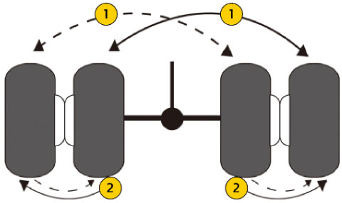
Tire Rotation Method
-
1
First Rotation: Perform 2-3 rotations until the tires are completely worn
-
2
Second Rotation: If possible, rotate tires between different axles for better results.When using dual tires, the inner tires usually bear more weight and absorb more heat from the brake drums.
Key Points of Tire Rotation
- Change the rolling direction
- Rotate between front wheels, trailer wheels, and drive axels
- Tire rotation frequency should be higher during the initial stage of wear
Effects of Tire Rotation
Example of a Standard Long Distance Truck Driver
A driver uses 3 test vehicles to perform tire rotation respectively at wear rates of 20%, 40%, and 60%. After analyzing the results, it is concluded that the optimal rotation approach is to have the load between 100-130% with a speed of 80km/h.
| Total Life * Cost/km | ||
|---|---|---|
| Optimal Position | 122 | 84 |
| Fixed Position | 100 | 100 |
Includes the extended tire life and cost for 2 tire rotations
Example of Overloading
180-320% 40-50km/h (actual tire life before failure)
| Actual Tire Life | Wear Rate | Tire Life Index | |
|---|---|---|---|
| Rotated Position | 49,700km | 82% | 260% |
| Fixed Position | 19,100km | 37% | 100% |
 Tire Pressure
-
40
-
70
-
90
-
100
 TEmperature
-
100
-
70
-
100
-
100
 Average Speed
-
125
-
100
-
75
-
50
 Vehicle Load
-
160
-
100
-
70
-
40
 Trailer Wheel Position
-
65
-
100
-
35
 Road Conditions
-
100
-
80
-
60
Retread tire mainly refers to retreading the tire crown.
Price Index
Price Index
Price Index
and Life Index
Price indices are only provided as examples.
Standard Rule
A
-
Retread Tire60-
Price Index -
Tire Casing Sell10=
Price Index -
50Retread Cost
Index
B
Under normal conditions, retreaded Giti tires can reach 80% of the mileage on new tires.
C
-
New Tire100x
Mileage and
Life Index -
80%.80=
-
80Retreaded Tire
Mileage and
Life Index
Saving even small amounts of fuel can provide a big benefit to your fleet’s bottom line! Find out some ways to improve mileage without sacrificing the performance of your truck tires.
Contact Us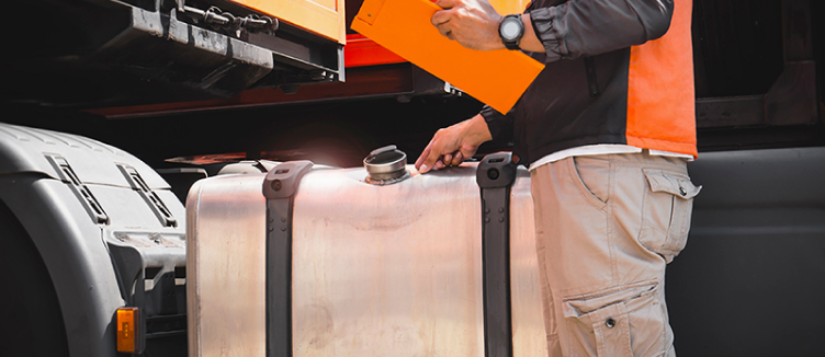
Vehicle Driving Resistance Includes
1

Inertia
When a vehicle changes motion, it must overcome the inertia force which depends on the value of the vehicle acceleration and weight.
2

Gravity
This is an inevitable natural force.
3

Air Resistance
This is primarily related to the vehicle’s aerodynamics, such as streamlined body design.
4

Mechanical Friction
This friction is inevitable and comes from the mechanical parts of the vehicle such as engine gear box, bearings, and brakes.
5

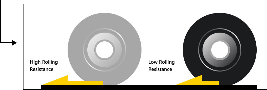
Tire Rolling Resistance – Driving Resistance That Is Ignored
Most people tend to ignore the 5th driving resistance – tire rolling resistance. However, it is actually the 3rd largest resistance that affects fuel consumption. When a truck in good condition is traveling at a speed of 80 km/h on a paved road, under standard load and pressure, about 26% of its power is used to overcome the tires’ rolling resistance. Therefore, the effect of tire rolling resistance on fuel consumption cannot be ignored.
Vehicles need to consume fuel to overcome driving resistance since fuel is the only power source. Therefore, Driving Resistance mus be reduced in order to save fuel.
Silica helps lower rolling resistance
Increase driving distance by about 6-7%

Low Rolling Resistance Tire

Standard Tire
With each rotation of the wheel, the tire becomes deformed due to the load. Since both the rubber and internal air are flexible, the tire will be subject to repeated compression and expansion when rolling. All these processes need to consume a certain amount of energy. Part of which is converted into heat and increases the tire temperature. This loss of energy is known as tire rolling resistance.
Silica helps lower rolling resistance
Advanced formula, structure, and pattern design lowers rolling resistance.
Ordinary Tire Formula

Ordinary Rubber Structure

Ordinary Rubber heats up when car br is motion
Low Rolling Resistance Tire Formula

Dispersed Carbon Black Structure

When travelling on the road, a tire with silicon and nano-sized carbon black reduces heat which in turns reduces rolling resistance.
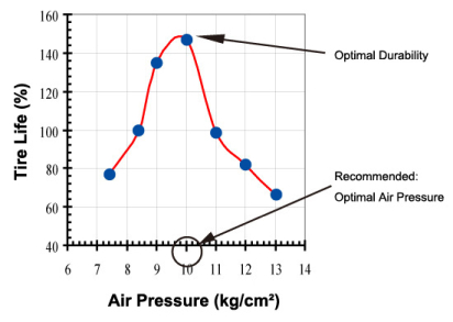
Maintain Proper Tire Pressure
Maintain the pressure of your tire to avoid danger.
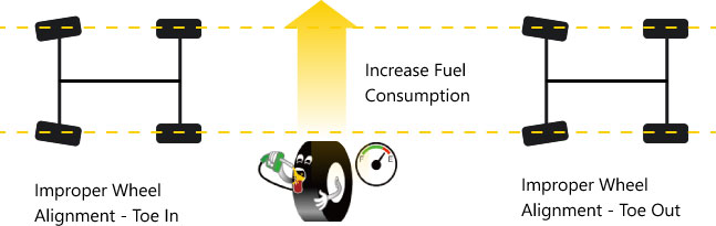
Maintain Proper Wheel Pressure
Avoid overloading to increase tire lifeand improve fuel efficiency

Giti Tire provides diverse tire solutions to meet the needs of various road conditions and driving habits for the domestic commercial vehicle market.
-
GTL922FS
Long Haul Coach All-Position
 Details
-
GSL229FS
Long Haul Coach All-Position
Details -
GDL633FS
Long Haul Coach All-Position
Details
Giti’s Low Rolling Resistance tires,
Find out some interesting, more advanced truck tire facts that can maximize your knowledge and driving success. These include facts on overloading hazards, wide base tires, nitrogen, and others.
Contact Us
Technology Identification and Benefits
Latest eco-friendly materials are used to reduce damage to the environment


Minimizes damage to the environment for better environmental protection
Lowers rolling resistance for better fuel efficiency
Minimizes stone retention and tire damage


Effectively reinforces bead to reduce bead failure

Optimized tire casing contour for uniform force distribution and better wear resistance


New high-strength casing material for stronger casing
Giti Tire’s retreadable casing structure design provides higher durability and efficiency
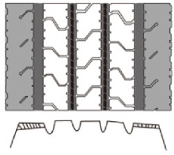
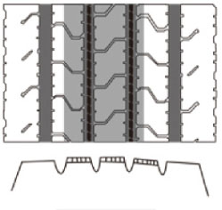
All Giti tires are regroovable and designed utilizing thicker groove rubber with a stronger rubber formula to extend tire life
Regroovable depth indicator is located inside the tread wear indicator for regrooving purposes

Several places are marked with TWI on the tread base (TWI located on the shoulder) to remind the driver of the tread condition and when to consider regrooving and retreading
During retreading, the reference rotation direction of the buffing machine helps prevent belt layers from damage and ensures quality retreads
Excellent wear resistance for higher mileage when traveling long distance at high speeds
Tread is more resistant to punctures, cuts, and chunks
Unique series of number for convenient identification and after sales claims with quality guarantee
Designated products included in the Nationwide Warranty Program brings you convenient claim settlement services
- Fuel Efficient, Eco-Friendly
- Higher Mileage
- Comfortable Drive
- Lower Cost
- Better Durability
- Improve Operational Efficiency
- Extend Tire Life
- Enhanced Safety
- Outstanding Service
Overloading will greatly reduce tire life
- 10%
- 20%
- 50%
- 100%
- 20%
- 35%
- 59%
- 85%
Gain a better understanding of the actual load of domestic truck tires to ensure proper tire pressure. See the Giti Tire Technical Book or ask your Giti Tire representative for more information.
| Tire Specification | Tire Pressure (kPa) |
1000 | 1100 | 1200 | 1300 | 1400 | 1500 |
|---|---|---|---|---|---|---|---|
| 10.00R20 | Single Tire Dual Tire |
3500 4500 |
4250 5000 |
5000 5500 |
6000 |
||
| 11.00R20 | Single Tire Dual Tire |
3500 5000 |
4500 5400 |
5500 5800 |
6200 |
6600 |
7000 |
| 12.00R20 | Single Tire Dual Tire |
4000 5500 |
5000 6000 |
6000 6500 |
7000 |
7500 |
8000 |
Over inflation will lead to tire blowout which affects driving safety and increases operating costs!
The Difference between Tube and Tubeless TIres
What Is a Tube Tire?
- Tire Consists of 3 Components: tire casing, tube, and flap
- Wheel consists of 5 components and is more susceptible to damage or failure due to the number of components
What Is a Tubeless Tire?
- Tubeless and tube tires have the same outer diameter so the gear ratio will remain the same before and after a tire change
- Rim diameter is 2 inches wider and has better heat dissipation; tire + rim = lower tire temperature
- Carries the same load but with a lighter rim
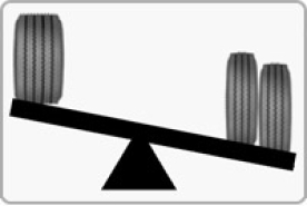
Tube vs Tubeless: Which One Is Better?
Tubeless Tire Is 10% Lighter Than a Tube Tire
Advantages of Tubeless Tires:
10% Lighter Than Tube Tires
-

Lower sidewalls provide more accurate and safer steering and handling
-

Fewer components, less friction, and lower rolling resistance for better fuel savings
-

Excellent heat dissipation leads to lower tire temperatures and longer tire life
-

Leveled rectangular contact areas have uniform wear and increase tire life
-

Fewer components lightens weight and reduces fuel consumption
Limitations of Tuber Tire

Too many components lead to lower rolling efficiency

Increased fuel consumption

Poor heat dissipation leads to higher tire temperatures and shorter tire life

Ovate contact areas are more susceptible to partial wear

Too many components increases weight

Deflates rapidly when punctured
Tubeless Tires Reduces Operational Costs
| Wheel Position | Steering Wheel |
Drive Axle |
Trailer Wheel |
Spare Tire |
Total |
|---|---|---|---|---|---|
| Numbers of Tires | 2 | 8 | 12 | 2 | 24 |

| Item | Tire Price (USD) |
Rim Price (USD) |
Total |
|---|---|---|---|
| Tube Tire | 443 | 85 | 528 |
| Tubeless Tire | 410 | 80 | 490 |
| Price Difference | 33 | 5 | 230 |
| Number of Tires | 24 | 24 | 24 |
| Total Price Difference | 792 | 120 | 912 |
Tubeless Tires Improve Vehicle Safety and Handling

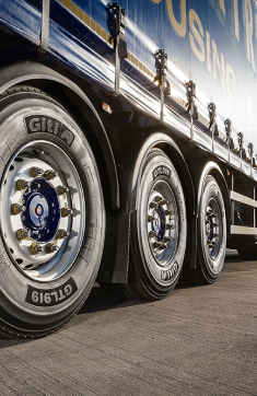
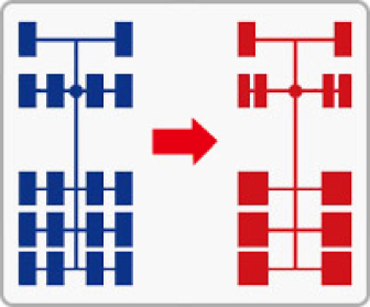
Wide Base Tires Are Safer, More Economical, and More Eco-Friendly
Utilizes radial, optimal aspect ratio, and tubeless techniques to optimize tire performance and replace regular dual tires.
5 Advantages
Lighter Vehicle Weight for Higher Load Capability
- Wide base tires are lighter than dual tires (i.e. lighter by 30% for 1-1-3 vehicle models)
- Reduced tire weight can be converted into load capability to bring more economic benefits (i.e. more than RMB 20,000 worth of benefits can be calculated per vehicle per year for 1-1-3 vehicle models)
Better Fuel Efficiency Lowers Cost
- Giti Tire’s tests in Yunnan have proven that wide base tires can save more than 4% fuel when compared to dual tires
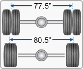
Wider Wheelbase and Lower Center of Gravity for Safer and Easier Handling
- Wheelbase of single tires is about 4% more than that of dual tires
- Wider wheelbase and lower center of gravity improve vehicle stability for safer and easier handling
Easier Installation for Higher Operational Efficiency
- Using the 1-1-3 vehicle model as example, installing 6 single tires on the trailer wheel position is equivalent to installing 12 dual tires which greatly reduces both installation and maintenance time
- When installing dual tires, tires with different air pressure on the same axle will lead to uneven load and wear which affects operational efficiency
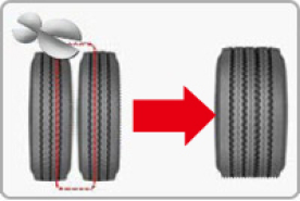
Better Heat Dissipation Enhances Tire Life
- Wide base tires have two fewer sidewalls than dual tires, generates less heat, enhances heat dissipation, increases tire wear resistance, and improves tire life


What is Nitrogen?
- Nitrogen (N2) is colorless and tasteless
- Has low thermal conductivity
- Nitrogen molecules are larger than oxygen molecules
- Nitrogen is stable and does not easily react with other substances at room temperature

Advantages of Nitrogen Filled Tires:

Nitrogen’s low thermal conductivity decelerates heat accumulation and significantly reduces tire blowouts
-
Nitrogen molecules are larger than oxygen molecules and penetrate the tire wall slower than air
-
Does not contain water or other substances which effectively inhibits the tire and rim from slowly oxidizing and corroding
-
Nitrogen slows tire pressure loss, decreases tire temperature, and reduces rolling resistance caused by insufficient air pressure and high tire temperatures